IPC-A-610 and J-STD-001: Understanding PCBA Quality Standards
Every PCB assembly that leaves a factory is judged against a quality standard — whether you know it or not. The two standards that define what "acceptable" means in electronics manufacturing are IPC-A-610 (Acceptability of Electronic Assemblies) and J-STD-001 (Requirements for Soldered Electrical and Electronic Assemblies). Together they form the foundation of quality assurance for virtually every PCBA produced worldwide. If you're buying PCB assemblies, understanding these standards is the difference between receiving boards that work — and boards that work for years under punishing conditions.
What Is IPC-A-610?
IPC-A-610 is the most widely used inspection standard in the electronics industry. Published by the Association Connecting Electronics Industries (IPC), it defines the visual acceptability criteria for finished electronic assemblies. In plain terms: it's the book inspectors use to decide whether a solder joint, component placement, or PCB surface condition passes or fails.
The standard covers virtually every physical attribute of a completed assembly: solder joint shape and wetting, component alignment and orientation, cleanliness, laminate conditions, discrete wiring, and markings. For each attribute, IPC-A-610 provides illustrated examples of what constitutes a target condition, an acceptable condition, and a defect condition. This three-tier visual reference system removes ambiguity — an inspector in Shenzhen and an inspector in Stuttgart can look at the same joint and reach the same conclusion.
Critically, IPC-A-610 is not a manufacturing process standard. It tells you what the end result should look like, not how to achieve it. That's where J-STD-001 comes in.
The Three IPC Classes
IPC-A-610 defines three product classes that correspond to increasing levels of reliability and cost. The class you choose has a direct impact on your manufacturing yield, rework rate, and per-unit price.
Class 1 — General Electronic Products
Class 1 covers products where the primary requirement is functionality. As long as the device works, cosmetic imperfections and less-than-perfect solder joints are acceptable. Typical Class 1 products include inexpensive consumer toys, promotional giveaways, and disposable electronics. Defects that don't impair function — such as minor solder splatter, slightly disturbed joints, or non-critical component misalignment — are permissible. The trade-off is cost: Class 1 is the cheapest to manufacture because it tolerates the widest range of variation.
Class 2 — Dedicated Service Electronic Products
Class 2 is the industry workhorse. It applies to products where extended life and uninterrupted service are desirable but not mission-critical. Think laptops, televisions, industrial controllers, automotive infotainment systems, and consumer appliances. Class 2 tightens the criteria considerably: solder joints must exhibit proper wetting, component placement tolerances are stricter, and cosmetic conditions that could indicate latent reliability problems are rejected. Most commercial electronics are built to Class 2. It balances reliability with reasonable manufacturing cost.
Class 3 — High Performance / Harsh Environment Electronic Products
Class 3 is the highest tier of IPC-A-610. It governs products where failure is simply not an option — life-support medical devices, avionics, military equipment, space systems, and critical infrastructure. Every solder joint must meet near-perfect criteria. Barrel fill in plated through-holes must reach 75% minimum (versus 50% for Class 2). Surface mount joints must have precise fillet dimensions. Even minor cosmetic issues that pose no functional risk are rejected if they deviate from the standard. The cost premium is significant — Class 3 assemblies can cost 30–50% more than Class 2 equivalents due to slower production speeds, higher inspection burden, and increased rework.
Class 1, 2, and 3: At a Glance
| Criterion | Class 1 — General | Class 2 — Dedicated Service | Class 3 — High Performance |
|---|---|---|---|
| Reliability requirement | Functional at shipment | Extended life, uninterrupted service | Continuous performance; failure is not permitted |
| Typical products | Toys, disposable electronics | Laptops, appliances, industrial controls | Medical devices, avionics, military, space |
| Solder joint fillet | Wetting evident; shape not critical | Smooth, proper wetting angle | Precise fillet dimensions; no anomalies |
| PTH barrel fill | Not specified | ≥ 50% vertical fill | ≥ 75% vertical fill |
| Component placement | Functional; generous tolerance | Tighter tolerance; good alignment | Precise placement; minimal offset |
| Cleanliness | No conductive residues | No visible residues | Stringent; often requires ionic cleanliness testing |
| Rework allowed | Yes, if functional | Yes, with limits per IPC-7711/7721 | Limited; strict rework documentation required |
| Relative cost | Baseline | +10–20% over Class 1 | +30–50% over Class 2 |
What Is J-STD-001?
If IPC-A-610 is the inspector's rulebook for the finished product, J-STD-001 is the process engineer's manual for how to solder. Developed jointly by IPC and the Electronic Industries Alliance (EIA), J-STD-001 specifies the materials, methods, and verification criteria for producing high-quality soldered interconnections.
J-STD-001 covers the full soldering process: solder alloy selection, flux types, thermal profiles, hand soldering techniques, machine soldering parameters, and even operator training and certification. It defines three product classes that align with IPC-A-610's classes, but from a process perspective. Where IPC-A-610 says "the joint must look like this," J-STD-001 says "use this solder alloy at this temperature with this dwell time to achieve a joint that meets the requirement."
The standard also mandates operator proficiency. J-STD-001 requires that anyone performing hand soldering on Class 3 products be formally trained and certified — passing both written exams and practical workmanship demonstrations. This training requirement is one reason Class 3 assembly commands a premium: not just any operator can build your boards.
IPC-A-610 vs J-STD-001: Key Differences
While the two standards work together, confusing them leads to costly mistakes. Here's how they differ:
- Scope. IPC-A-610 is an acceptance standard for finished assemblies. J-STD-001 is a process standard for soldering operations. The former tells you what to reject; the latter tells you how to build it right in the first place.
- Focus. IPC-A-610 covers all visual attributes of an assembly — solder joints, yes, but also component mounting, cleanliness, markings, and laminate condition. J-STD-001 focuses almost exclusively on the solder joint itself: materials, process parameters, and joint geometry.
- Audience. IPC-A-610 is written for quality inspectors, QA managers, and end customers who need to verify acceptable work. J-STD-001 is written for process engineers, manufacturing technicians, and operators on the production floor.
- Relationship. J-STD-001 is the build standard; IPC-A-610 is the accept standard. A board built to J-STD-001 should pass IPC-A-610 inspection, but IPC-A-610 covers more ground and may catch issues that J-STD-001 doesn't address.
Think of it this way: J-STD-001 is the recipe, and IPC-A-610 is the photograph of the finished dish. A good recipe helps you produce a beautiful plate — but the photograph is what the customer uses to decide if it's acceptable.
Why Class 2 vs Class 3 Matters for Cost
The jump from Class 2 to Class 3 isn't just a paperwork exercise — it materially changes how your boards are built. Class 3 demands tighter process controls at every step:
- Stencil printing. Solder paste deposition must be more precise, requiring finer stencil apertures and more frequent cleaning cycles. Paste volume variation that's tolerable at Class 2 becomes a defect risk at Class 3.
- Pick-and-place. Component placement tolerances tighten, which can slow placement speed as machines take extra time to verify positioning. Some high-speed chip shooters must run at reduced throughput.
- Reflow profiling. Oven profiles must be validated more rigorously, with tighter soak and reflow windows. Multi-zone ovens need more thermocouple monitoring points, and profiles are revalidated more frequently.
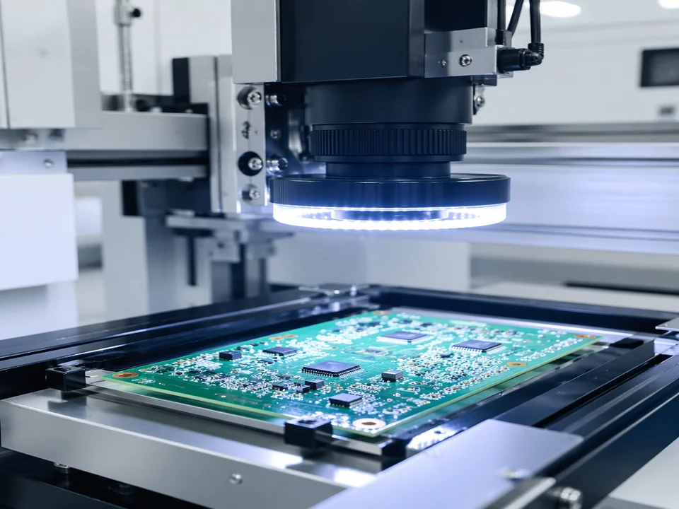
- Inspection. Class 3 typically requires 100% AOI (Automated Optical Inspection) and often adds X-ray inspection for BGAs and QFNs. Manual visual inspection alone, common at Class 2, is insufficient.
- Rework. The rework rate is higher because borderline joints that would pass Class 2 are rejected at Class 3. Rework itself must follow stricter procedures under IPC-7711/7721.
The cumulative effect is a 30–50% cost increase. For a 1,000-unit production run, you need to weigh whether that premium is justified. For a consumer IoT sensor that will sit in an air-conditioned office, Class 2 is almost certainly sufficient. For a ventilator control board that keeps a patient alive, Class 3 is non-negotiable.
Specifying Quality Requirements in Your RFQ
Vague quality language in a request for quotation is one of the most common — and expensive — mistakes buyers make. A phrase like "build to high quality" means nothing on the factory floor. Here's how to specify quality unambiguously:
- State the standard and class explicitly. Write "Assemble to IPC-A-610 Class 2, soldering per J-STD-001 Class 2" — not "good quality." If your product is Class 3, say Class 3. If different sections of the board require different classes (common in mixed-use assemblies), specify which areas are which.
- Reference the revision. IPC standards are updated regularly. IPC-A-610 is currently on Revision H (2020); J-STD-001 is on Revision H (2020) as well. Specifying the revision ensures the manufacturer builds to the same version your design was validated against.
- Define acceptance sampling. Specify the AQL (Acceptable Quality Limit) and sampling plan (typically ANSI/ASQ Z1.4). For Class 3, an AQL of 0.65 or tighter is common. For Class 2, AQL 1.0 or 1.5 is typical. Don't leave sampling to chance.
- List required inspection methods. If you need X-ray for BGAs, flying probe testing, or ionic contamination testing per IPC-TM-650, call it out in the RFQ. These are not automatic — you must ask for them.
- Specify documentation deliverables. Require first-article inspection reports (FAIR) per AS9102 (for aerospace/military) or IPC standard formats. Ask for solder paste inspection (SPI) data and AOI reports. Documentation is your proof that the standard was followed.
A well-written quality section in your RFQ protects both you and the manufacturer. It sets clear expectations, eliminates ambiguity during incoming inspection, and provides a contractual basis for resolving disputes.
Which Standard Should You Reference?
The short answer: both. IPC-A-610 for acceptance criteria and J-STD-001 for process requirements. They are complementary, not competitive. A competent manufacturer will have both standards in-house and their operators will be trained to both. If a CM (contract manufacturer) can't tell you which class they build to — or worse, can't produce their J-STD-001 training records — walk away.
Need IPC Class 3 assembly? Send us your specs.
uppcba builds to IPC-A-610 Class 2 and Class 3, with J-STD-001 certified operators on every line. Full AOI, X-ray, and FAIR documentation included.
Request a Quote